Cemented resistors
Application:
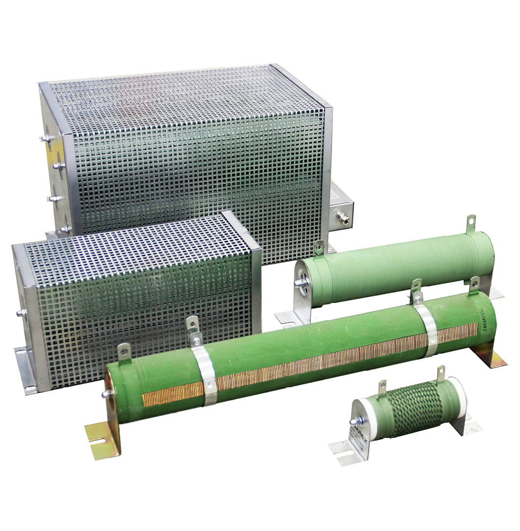
RC resistors are basic structure of wire and band resistors mostly used as braking, power and load resistors with power ranging from 300 W up to 10000 W. They are designed mainly for indoor use.
Parameters:
| continuous power range | 300 W – 10 000 W |
| continuous current range | RC1: 0,4 A – 15 A; RC2: 0,4 A – 30 A; RC4: 0,4 A - 60 A |
| resistance range | resulting from power and work current |
| operating voltage | up to 1000 V AC/DC |
| insulation withstand voltage | 2500 VAC / 1 min. |
| ambient max./min. temperature | -5°C / 55°C |
| installation conditions of resistor | installed indoors, in places where air exchange is ensured |
| level of protection | IP00 – IP20 (for special applications - IP23) |
| temperature of resistor’s surfece for continuous operation | 390°C ± 15°C |
Construction:
The construction of RC resistors consists of a ceramic shaft on which the wire or the band is wound, depending on the load. The whole is covered with special white clay resistant to high temperatures. The advantage of white clay is the lack of smoke on first use.
Operating conditions:
- continuous, cyclical, pulse operating
- indoor use
- work in an atmosphere containing no explosive gases and mixtures and corrosive fumes
- ambient temp.: lowest long-term -30°C, the highest 24-hour 30°C, the highest short-term 55°C
- relative humidity to 95% at +22°C (293 K)installation height max. 1000 meters above sea level
Compliance with standards:
- PN-EN 60947-1
- PN83-H92336
- PN-EN 60071-1
- PN-EN 60529
Resistors RC1: power range 300 W – 2500 W for current 0,4 A – 15 A:
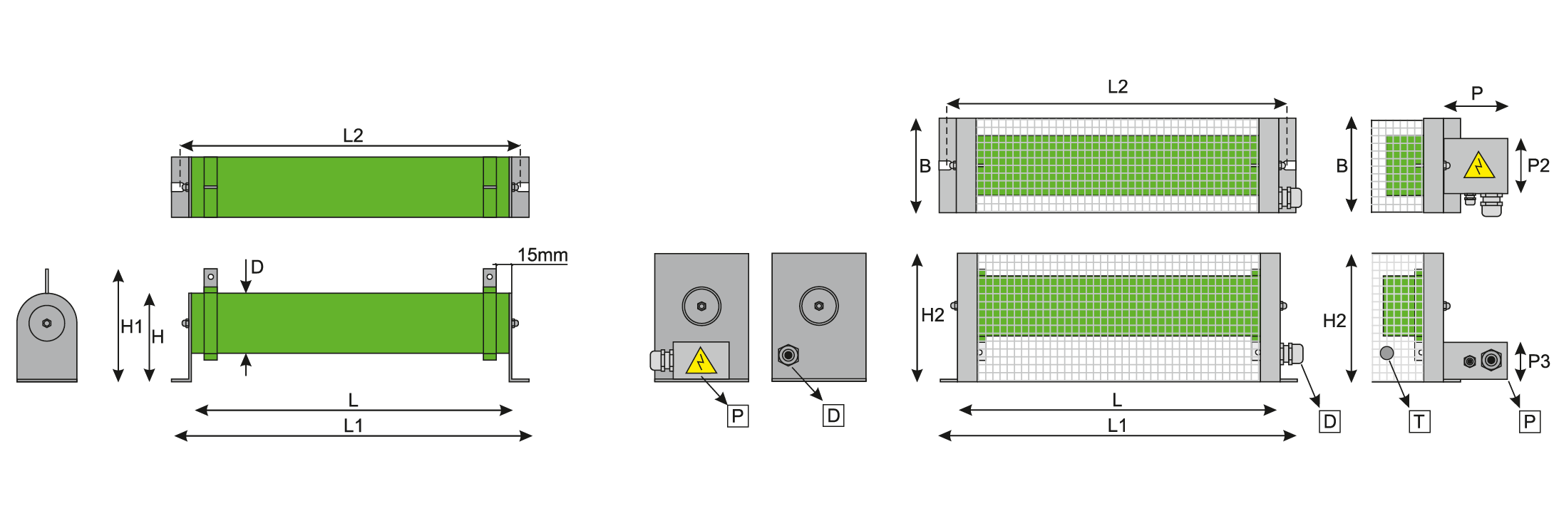
| POWER [W] | Rmax. [Ω] | Rmin. [kΩ] | D | L | L1 | L2 | H | H1 | H2 | B | P | P2 | P3 |
| 300 | 1,5 | 1,7 | 50 | 150 | 220 | 190 | 70 | 100 | 120 | 100 | 80 | 65 | 50 |
| 400 | 2 | 2,2 | 50 | 200 | 260 | 230 | 70 | 100 | 120 | 100 | 80 | 65 | 50 |
| 500 | 2,4 | 2,8 | 50 | 230 | 290 | 260 | 70 | 100 | 120 | 100 | 80 | 65 | 50 |
| 600 | 2,9 | 3,3 | 50 | 280 | 340 | 310 | 70 | 100 | 120 | 100 | 80 | 65 | 50 |
| 700 | 3,4 | 3,9 | 50 | 320 | 380 | 350 | 70 | 100 | 120 | 100 | 80 | 65 | 50 |
| 800 | 3,9 | 4,5 | 70 | 300 | 360 | 330 | 100 | 130 | 155 | 125 | 80 | 90 | 50 |
| 1000 | 4,9 | 5,6 | 70 | 300 | 360 | 330 | 100 | 130 | 155 | 125 | 80 | 90 | 50 |
| 1250 | 6,1 | 7 | 70 | 360 | 420 | 390 | 100 | 130 | 155 | 125 | 80 | 90 | 50 |
| 1500 | 7,3 | 8,4 | 70 | 410 | 470 | 440 | 100 | 130 | 155 | 125 | 80 | 90 | 50 |
| 2000 | 9,8 | 11,2 | 70 | 600 | 660 | 630 | 100 | 130 | 155 | 125 | 80 | 90 | 50 |
| 2500 | 12,2 | 14 | 70 | 600 | 660 | 630 | 100 | 130 | 155 | 125 | 80 | 90 | 50 |
Resistors RC2: power range 600 W – 5000 W for current 0,4 A – 30 A:
| POWER [W] | Rmax. [Ω] | Rmin. [kΩ] | D | L | L1 | L2 | H | H1 | H2 | B | P | P2 | P3 |
| 600 | 0,7 | 3,3 | 50 | 160 | 220 | 190 | 70 | 100 | 120 | 125 | 80 | 65 | 50 |
| 800 | 1 | 4,5 | 50 | 200 | 260 | 230 | 70 | 100 | 120 | 125 | 80 | 65 | 50 |
| 1000 | 1,2 | 5,6 | 50 | 230 | 290 | 260 | 70 | 100 | 120 | 125 | 80 | 65 | 50 |
| 1200 | 1,5 | 6,7 | 50 | 280 | 340 | 310 | 70 | 100 | 120 | 125 | 80 | 65 | 50 |
| 1400 | 1,7 | 7,8 | 50 | 320 | 380 | 350 | 70 | 100 | 120 | 125 | 80 | 65 | 50 |
| 1600 | 2 | 9 | 70 | 300 | 360 | 330 | 100 | 130 | 155 | 165 | 80 | 90 | 50 |
| 2000 | 2,4 | 11 | 70 | 300 | 360 | 330 | 100 | 130 | 155 | 165 | 80 | 90 | 50 |
| 2500 | 3,1 | 14 | 70 | 360 | 420 | 390 | 100 | 130 | 155 | 165 | 80 | 90 | 50 |
| 3000 | 3,7 | 16,8 | 70 | 410 | 470 | 440 | 100 | 130 | 155 | 165 | 80 | 90 | 50 |
| 4000 | 4,9 | 22 | 70 | 600 | 660 | 630 | 100 | 130 | 155 | 165 | 80 | 90 | 50 |
| 5000 | 6,1 | 28 | 70 | 600 | 660 | 630 | 100 | 130 | 155 | 165 | 80 | 90 | 50 |
Resistors RC4: power range 1200 W – 10000 W for current 0,4 A – 60 A:

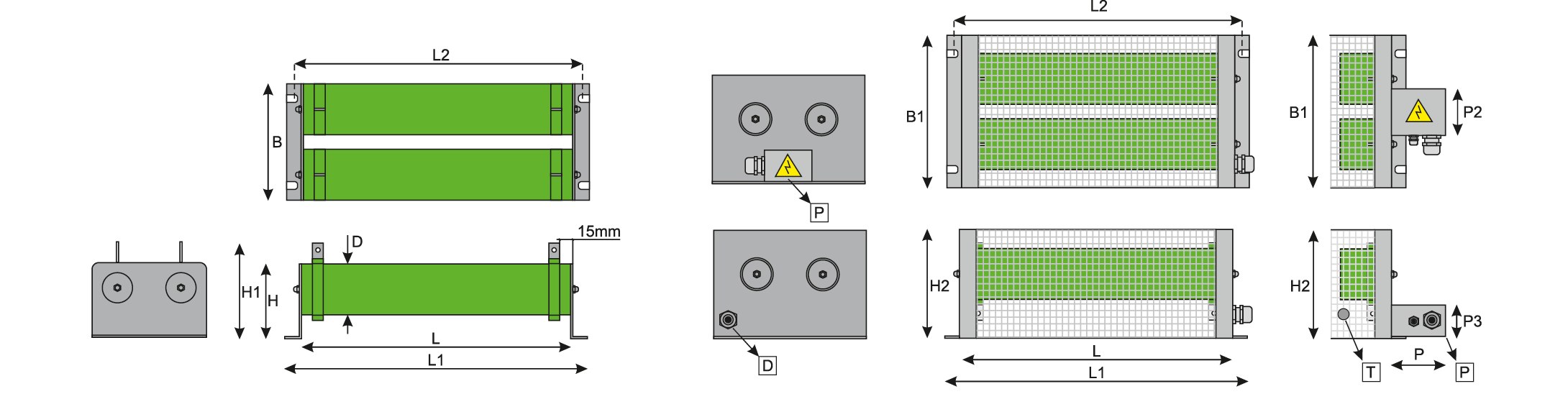
| POWER [W] | Rmax. [Ω] | Rmin. [kΩ] | D | L | L1 | L2 | H | H1 | H2 | B | P | P2 | P3 |
| 1200 | 0,4 | 6,7 | 50 | 160 | 220 | 190 | 190 | 190 | 8 | 65 | 50 | 65 | 50 |
| 1600 | 0,5 | 9 | 50 | 200 | 260 | 230 | 190 | 190 | 80 | 65 | 50 | 65 | 50 |
| 2000 | 0,6 | 11,2 | 50 | 230 | 290 | 260 | 190 | 190 | 80 | 65 | 50 | 65 | 50 |
| 2400 | 0,7 | 13,5 | 50 | 280 | 340 | 310 | 190 | 190 | 80 | 65 | 50 | 65 | 50 |
| 2800 | 0,9 | 15,7 | 50 | 320 | 380 | 350 | 190 | 190 | 80 | 65 | 50 | 65 | 50 |
| 3600 | 1 | 18 | 70 | 300 | 360 | 330 | 260 | 230 | 80 | 90 | 50 | 90 | 50 |
| 4000 | 1,2 | 22,5 | 70 | 300 | 360 | 330 | 260 | 230 | 80 | 90 | 50 | 90 | 50 |
| 5000 | 1,5 | 28 | 70 | 360 | 420 | 390 | 260 | 230 | 80 | 90 | 50 | 90 | 50 |
| 6000 | 1,8 | 33,7 | 70 | 410 | 470 | 440 | 260 | 230 | 80 | 90 | 50 | 90 | 50 |
| 8000 | 2,4 | 45 | 70 | 600 | 660 | 630 | 260 | 230 | 80 | 90 | 50 | 90 | 50 |
| 10000 | 3,1 | 56 | 70 | 600 | 660 | 630 | 260 | 230 | 80 | 90 | 50 | 90 | 50 |
Marking:
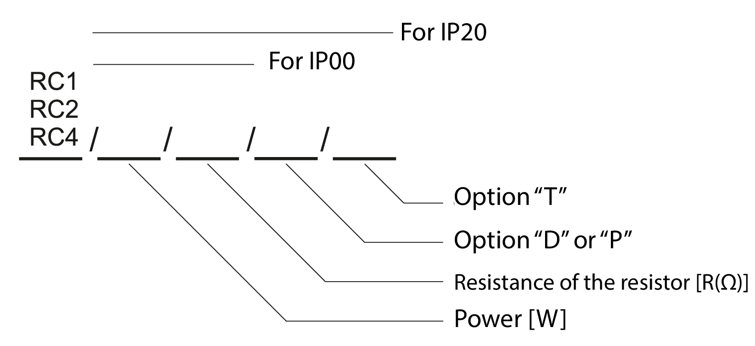
Examples:
RC1 / 1500W / 20R – resistor IP00, 1500 W, resistance 20 Ω
RC2 / 2000W / 3,5R / D – resistor IP20, 2000 W, resistance 3,5 Ω, connecting cables by the gland in the housing
RC4 / 4000W / 30R / P / T – resistor IP20, 4000 W, resistance 30 Ω, connection of the cables to the connection box, the resistor has thermal (T)
Selection of resistor power - continuous work:
RC resistors are made in such a way that the hottest section of the resistor does not heat up to a temperature higher than 400°C. When the lower temperature of the hottest section of resistor is needed, you have to increase the power of assorted resistor - 390°C = Pn; 350°C = 1,3Pn. The resistor reaches its maximum temperature in 30 min of countinuous load by rated power Pn. 90% of the temperature is reached after approx. 20 minutes of continuous operation. Overloaded resistor - loaded by the power twice bigger than the rated power, reaches 650°C, but there is no permanent demage.The resistor works just as well in intermittent cycle. In such situation it can withstand the higher power than the rated power. The method of selecting the power of the resistor for circular operating is shown in the following tables.

For proper selection you have to specify parameters:
Tz – time of switching
Tc – time of the cycle (switching + pause)
Then calculate the type of work [%] of the resistor.
Type of work = Tz/Tc × 100%

Impulse operation is when the resistor is temporarily overloaded by the power higher than the rated power and the next impulse occurs when the resistor is fully cooled, it means not earlier than after approx. 20 min. For proper selection of resistor’s power you need determine the duration of the impulse. Then, using the graph read the value of the overload power Pn for the specified time.
All technical data presented in the catalog can be changed due to technological progress.
Download:
Generate a catalog card (beta):