Motor drive with worm gear NS-EL 30
Application:
Motor drive type NS-EL is designed to work with disconnectors, load break switches, and medium voltage earthing switches in indoor conditions. The application of the drive allows for remote or local controlv of the switch installed in the cell of the switchgear. The NS-EL can easily replace the pneumatic or manual drive type NR1-01, introducing a new standard of control and safety (remote, local or manual control possibility).
Advantages:
- simple construction with the use of
- well-tested mechanisms (2000 switching cycles)
- high torque for easy manoeuvring of a wide range of medium-voltage switchgear (disconnectors, load break switches, earthing switches)
- operating reliability
- smooth adjustment of the angle of rotation of the output shaft in the range of 220°
- easy replacement of the manual drive with the NS-EL, without having to change the existing switchgear
- in the case of a power failure, manual operation is possible
Technical data:
| Motor type | with permanent magnets |
| Rated voltage of the motor | 24 / 110 / 220 VDC |
| Rated power | 90 - 300 W |
| Motor’s rated current | 0,5 A |
| Torque on the drive’s shaft | 35 - 70 Nm |
| Rated mechanical durability | 2000 cycles |
| Weight | from 8 kg (depending on chosen motor) |
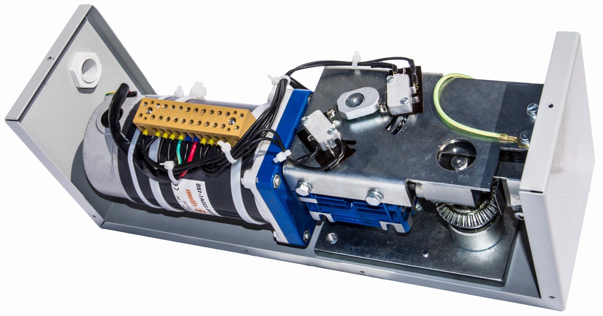
Design and operation:
The motor drive unit consists of:
- multi-degrees cylindrical - worm gear driven by DC series motor
- limit switches switching off the motor power supply when the main shaft reaches the assumed rotation angle
- terminal strip for connection of power supply and control circuits
- a microswitch for electrical interlock to disconnect motor power during manual operation
The housing is made of steel sheet, covered by epoxy powered paint. The lid is mounted to the drive’s panel with 2 bolts. There is the straight-though joint in the bottom, which allows to lead the conductors to the control system.
The drive mechanism includes:
- the motor with permanent magnets
- intersecting axis worm gear
- intersecting axis rack – type gear for manual opening
The electric motor drives a shaft through a worm gear which is clamped together by means of a fork. The rotation angle of the output shaft is limited by limit switches to 220°. The angle of rotation of theoutput shaft is adjusted by means of limit switches mounted on the distribution finger plate. Byloosening the M3 screw, the angle of the output shaft can be infinitely adjusted up to 220°.
Manual control:
To operate the drive:
- pull out the damper (placed upper or on the left side) which blocks the hole in the left side, that causes the blockade of the operating of electric motor
- insert the crank in the hole (which opens when pulling out the damper)
- rotate right (to close) or left (to open)
- after pulling out the operating lever, it is necessary to insert the damper to unlock the motor for electrical operating
Installation:
The drive is fastened to the support structure using two M10 screws. The wall on which the drive is mounted should be sufficiently rigid, ensuring a certain transfer of the electric manoeuvring torque.
TECHNICAL DRAWINGS, wiring diagrams:


Declaration of conformity:
All technical data presented in the catalog can be changed due to technological progress.
Download:
Generate a catalog card (beta):