ONE III 72,5 kV, ONE III 123 kV - outdoor disconnectors
Application:
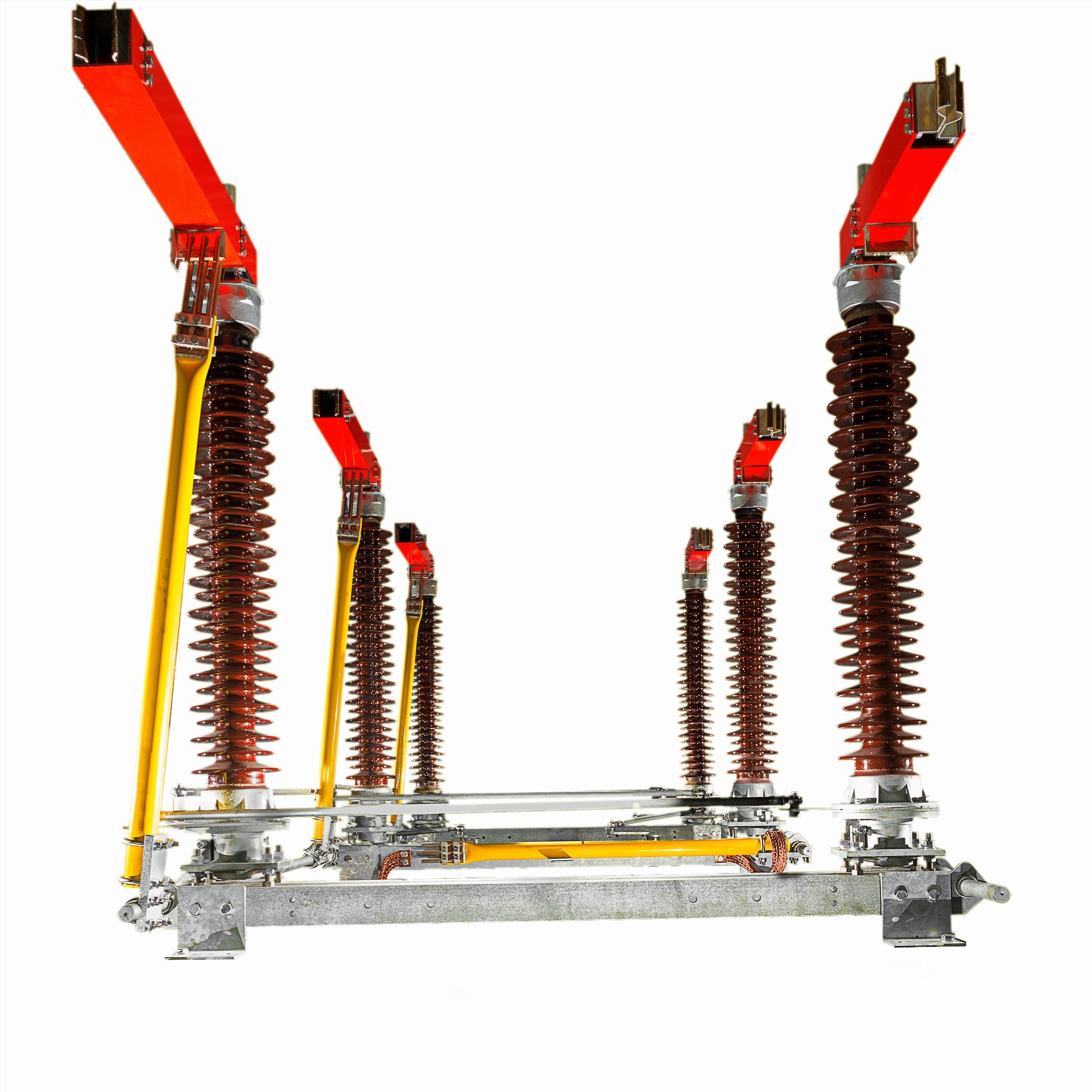
Outdoor disconnectors ONE III are designed for use in high-voltage outdoor switchgears. They open and close electrical circuits in the absence of current flow or when a small amount of current flows, and there is no voltage change between the poles. The disconnector in open provides visible isolating clearance and in close conducts work and short circuit currents. The devices equipped with the earthing switch grounds the parts of the circuit in which there is no voltage.
Disconnectors can be used as a single-pole connectors (with individual drive of each pole) or three-pole connectors with a single common drive.
In ELTOM's offer you can also find the drive for the ONE disconnector NSO 110.
Advantages:
- simple design
- high switching durability
- easy to use
- good technical and operational parameters
- the opportunity to join the drive at any pole
- very good protection against corrosion (galvanized steel or stainless steel parts)
- compensation the deflection of insulator
- blocking the position of disconnector and earthing switch when closed and open by the transition of the dead point of the crank gear
Operating conditions:
|
PARAMETER |
VALUE |
|
ambient temperature:
|
|
|
altitude |
< 1000 m |
|
wind pressure |
< 700 Pa |
|
ice thickness |
< 10 mm |
|
max. relative humidity |
100,00% |
Construction:
The disconnector has monopolar, two-column horizontally rotating structure. The busbar (placed on the post insulators) consists of two sets of connectors- left and right, cooperating with each other. The terminals and central contacts are made of electrolytic copper covered with silver. Contact this design uses the additional influence of electrodynamic forces generated during the flow of short-circuit, causing additional pressure. Supply conduits are mounted to rotary terminals. The connection the conductors to the disconnector is provided by M12 bolts.
The basis of the disconnector is made of rigid frame, welded of steel sections. To the basis two bearing bodies are mounted and post insulators are bolted to that bodies. Regulating pins, mounted at the base of insulators provide smooth angle compensation. In the upper part of the rotary body are placed flat levers, which (with strings and crank shaft) makes transmission, providing simultaneous rotation of insulators of 90⁰.
Grounding blade is fixed to the lever mechanism providing the possibility of rotary motion. In the first stage, grounding blade is rotated to the vertical, and then is pushed into the permanent contact, which is located in the busbar. Copper connection connects lower end of the grounding blade to the basis of the disconnector.
Technical data:
|
PARAMETER |
VALUE |
VALUE |
|
rated operating voltage [kV] |
72,5 |
123 |
|
rated continuous current [A] |
1600 | 2500 |
1600 | 2500 |
|
peak current [kA] |
125 |
125 |
|
short circuit current 1 sec. [kA] |
50 |
50 |
|
test voltage of insulation (50 Hz) [kV]:
|
|
|
|
impulse test voltage of insulation [kV]:
|
|
|
|
radio interference voltage [µV] |
<1000 |
<1000 |
|
mechanical durability |
2000 |
2000 |
|
drive:
|
|
|
|
weight [kg]:
|
|
|
TECHNICAL DRAWINGS:


All technical data presented in the catalog can be changed due to technological progress.
DECLARATIONS OF CONFORMITY:
Download:
Generate a catalog card (beta):