PBLDC - interlocking relay DC
Application:
The interlocking relay is designed for continuous control of the voltage on busbars in tram and trolleybuses substationons, where the rated power supply is 600 VDC.
The system, operating with earthing’s locking coil, prevents earthing of the busbar, if the voltage drops below specific threshold. Voltage measurement is performed in cooperation with the post insulator equipped with resistive divider. Relay cooperates with insulators of 1,5 OHM resistance.
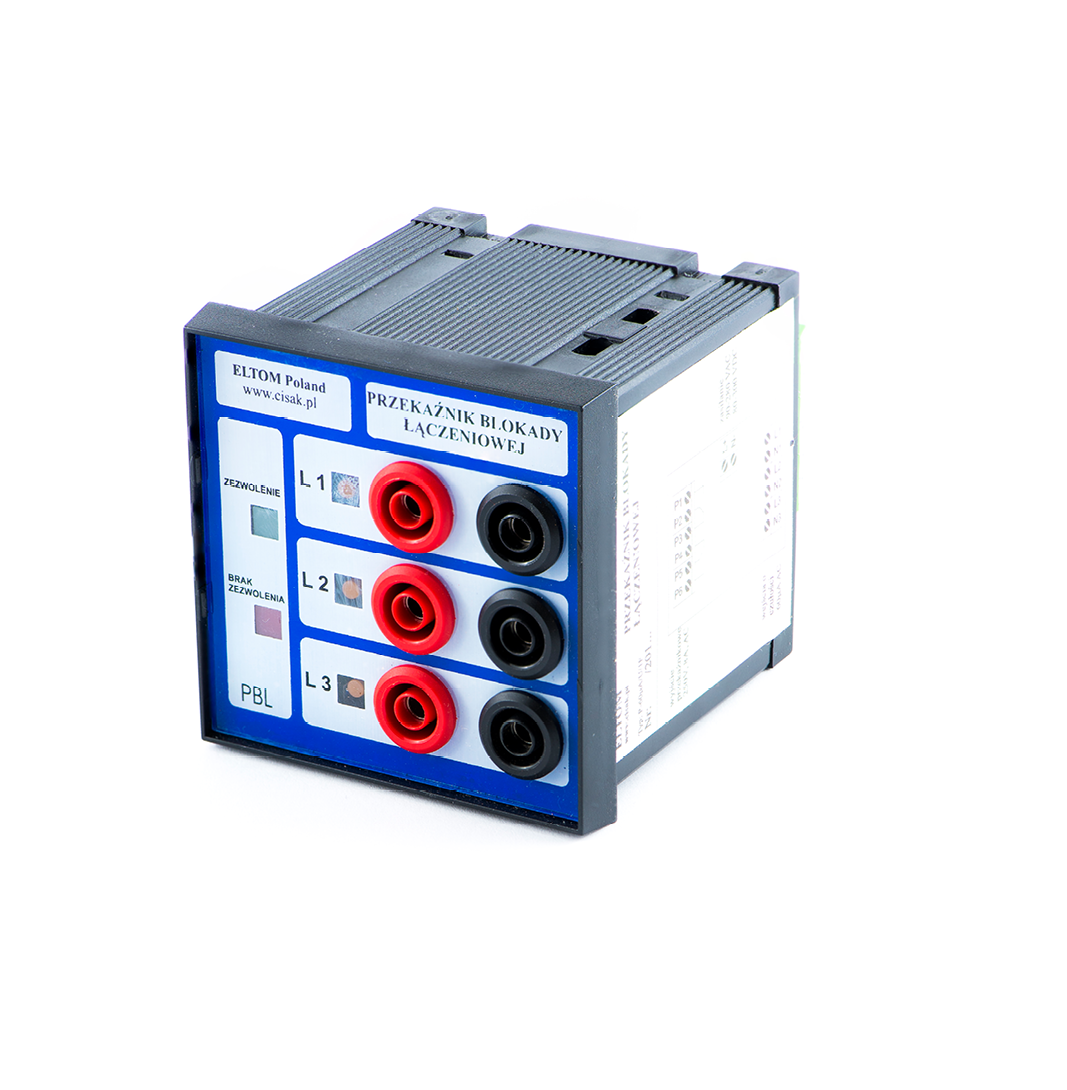
Housing:
The relay is made in the array housing 72x72x63 mm (material – noryl) prepared to mount on the switchgear’s door. Signal connection to the relay via a terminal clamping strips mounted on the rear side of the panel. The part of the output is a two-way relay with changeover contacts. On the front panel LEDs are positioned to reflect the state of the relay: green: authorization for the earthing, red: lack of authorization, orange: the presence of voltage on the busbar.
The front panel LEDs are placed to reflect the status of the relay:
- LED green: permission to grounding
- LED red: lack of permission to grounding
- LED orange: signaling the presence of voltage on the busbar
Operation:
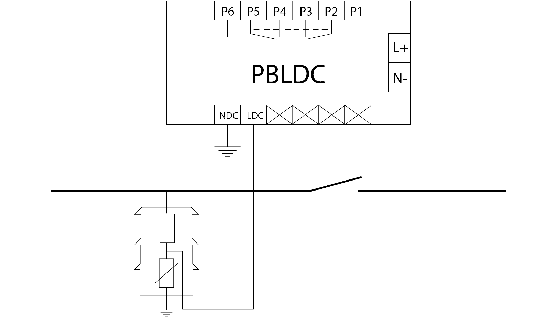
To the measuring input LDC there is signal leaded from the post insulator equipped with resistive divider. The negative pole is connected to the NDC.
If there is U>60VDC on the busbar:
- red LED is active
- the output relay is de-energized (closed contacts P2-P3, P5-P4)
If there is U<60VDC on the busbar:
- green LED is active
- the output relay is energized (closed contacts P2-P1, P5-P6)
Orange LED signals the presence of the voltage on the busbar. During the voltage is getting lower, the flash frequency is also getting lower.
For proper operation, the auxiliary power supply is needed for L+ and N- clamps. The lack of auxiliary power supply result in ‘lack of authorization’, on the front panel does not light up the LEDs.
Technical data:
| auxiliary power supply | 90 ÷ 280 VAC, 80 ÷ 300 VAC |
| power consumption | < 3 W |
| voltage threshold | 60 VDC |
| reaction time the disappearance or appearance of the voltage on the busbar | <1 s. |
Technical drawings:
All technical data presented in the catalog can be changed due to technological progress.
DECLARATIONS OF CONFORMITY:
Download:
Generate a catalog card (beta):